The internal battery controller
Here is the controller card charge extracted from the battery NOKIA BL-6Q and its circuitry.
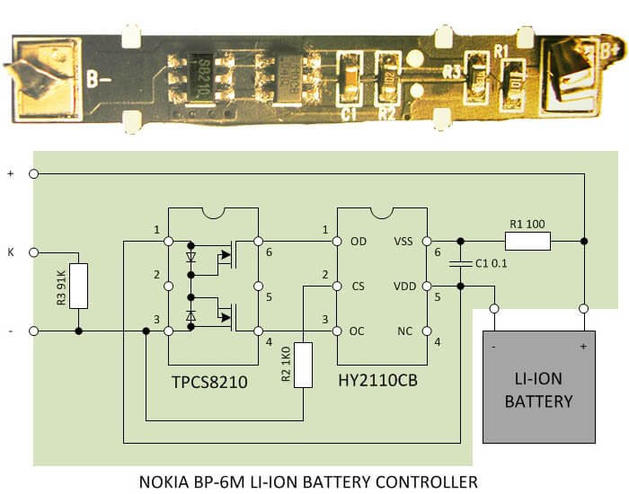
Let's see how it works. The battery is connected to two pins located on each side of the controller (B-and B +). On the circuit board, there are two chips - TPCS8210 and HY2110CB.
The task of the controller is to maintain the voltage on the battery in the range 4.3 - 2.4 volts to protect it against overcharge and overdischarge. In the normal discharge (or charge) HY2110CB chip output on the OD and OS High Voltage, which is slightly less than the battery voltage.
This voltage is holding open at FET chip TPCS8210, through which the battery is connected to the load (Your device).
If the battery discharges, as soon as the battery voltage drops below 2.4 volts, the work overdischarge detector circuit HY2110CB and the output voltage OD longer be issued. The top (the scheme) transistor circuits TPCS8210 closed and thus the battery is disconnected from the load.
When charging the battery once the battery voltage reaches 4.3 volts, the chip will work HY2110CB overcharge detector and the output voltage will not issue any OS. Bottom (under the scheme) transistor circuits TPCS8210 closed and the battery is also disconnected from the load.
An alternative method of replacing
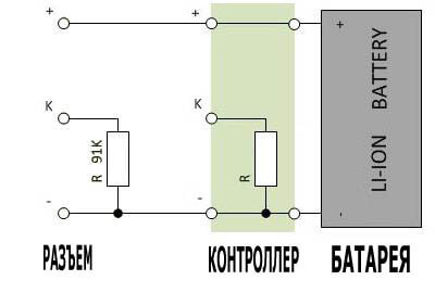
As can be seen from the scheme, none of the chip is no output for the transmission of information on the state of the battery in your device. The controller output is the "K" simply connected through a resistor for a specific value to the negative battery terminal. Therefore there is no "secret" information from the controller battery does not arrive.
At face value this resistor Your device can determine the type of the battery or shut down for non-compliance of the desired nominal values.
So for replacement of the battery to the battery of another manufacturer does not necessarily change the charge controller, simply measure the resistor standing between terminals "-" and "K" and connect the output of the "K" unit to the negative battery through an external resistor of the same value.
Documentation for the chip used in the controller can be HY2110CB download
here , and the chip TPCS8210 - here .
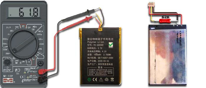
Consider , for example, an e-book LBOOK V5, as do the most accurate analog of the battery using knowledge about the structure of the charge controller . All work carried out in the following sequence:
- Find the battery from the cell phone, the closest to the native dimensions and capacity. In our case it’s NOKIA BL-4U. (In the right side of the picture)
- Cut off the wire from the native battery so that the remainder of the connector was enough for soldering a new battery, and the remainder of an old battery was enough for stripping conductors and measurement multimeter.
- Take any digital multimeter and set it on the measurement mode of resistance measurement limit - 200 Kohm. Connect it to the negative output and native controller battery. Measure the resistance.
- Turn off the multimeter. We are looking for the closest resistor at par . In our case - 62 Kohm.
- Solder the resistor between the negative terminal of the new battery and controller output wire on the connector. ( Yellow wire in the figure).
- Solder the connector terminals "+" and "-" respectively to the positive and negative terminal of the new battery . ( Red and black wires in the figure).
Back
